Testing Current Transformers (CTs) and Potential Transformers (PTs) typically involves verifying their performance characteristics, including accuracy, ratio, polarity, and insulation resistance.
Here’s an overview of how CT and PT testing is conducted on transformers:
- Preparation: Before conducting the tests, ensure that the transformer is de-energized and that all safety precautions are followed. Visually inspect the transformer for any signs of damage or deterioration.
- Ratio Test:
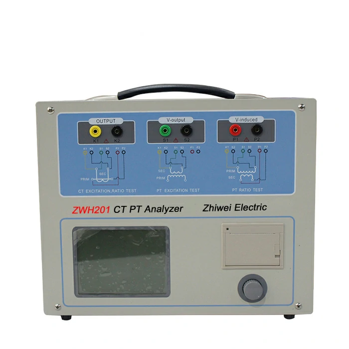
- CT Ratio Test: This test verifies the turns ratio of the CT by applying a known primary current and measuring the resulting secondary current. A CT ratio tester or secondary injection test set is typically used for this purpose. The measured ratio should match the nameplate or design specifications of the CT.
- PT Ratio Test: Similarly, the PT ratio test verifies the voltage ratio of the PT by applying a known primary voltage and measuring the resulting secondary voltage. The measured ratio should match the nameplate or design specifications of the PT.
- Polarity Test:
- CT Polarity Test: This test verifies that the polarity of the CT matches the intended direction of current flow. It involves injecting a test current into the primary winding and observing the direction of the resulting secondary current. ct pt tester The polarity should match the specified polarity indicated on the nameplate or in the design documentation.
- PT Polarity Test: For PTs, the polarity test verifies the alignment of the primary and secondary voltages. The test involves applying a known voltage to the primary winding and observing the resulting voltage polarity across the secondary winding. The observed polarity should match the specified polarity.
- Insulation Resistance Test:
- Both CTs and PTs should undergo an insulation resistance test to ensure the integrity of their insulation systems. This test involves applying a high DC voltage between the windings and the transformer tank or ground and measuring the resulting insulation resistance. A megohmmeter or insulation resistance tester is typically used for this test.
- Burden Test (CTs):
- CTs may also undergo a burden test to verify their performance under load conditions. This test involves connecting a burden box or load resistor to the secondary winding and measuring the resulting secondary current. The measured current should match the expected current based on the burden resistance and the CT ratio.
- Verification of Accuracy Class:
- Finally, the accuracy class of the CT or PT should be verified to ensure that it meets the required accuracy standards for the intended application. This may involve comparing the test results to the accuracy class specifications provided by the manufacturer or industry standards.
- Documentation:
- Document all test results, including ratio measurements, polarity, insulation resistance values, and any deviations from expected values. This documentation is essential for maintaining records of transformer performance and for troubleshooting any issues that may arise in the future.
By following these steps, CT and PT testing can be conducted effectively to verify the performance and reliability of transformers in electrical power systems.