What safety features are built into the dielectric strength of oil?

Dielectric strength testing of oil, particularly insulating oil used in electrical equipment such as transformers, involves assessing its ability to withstand electrical breakdown under high voltage conditions. Several safety features are built into the dielectric strength testing process to ensure the safety of operators and equipment.

These safety features may include:

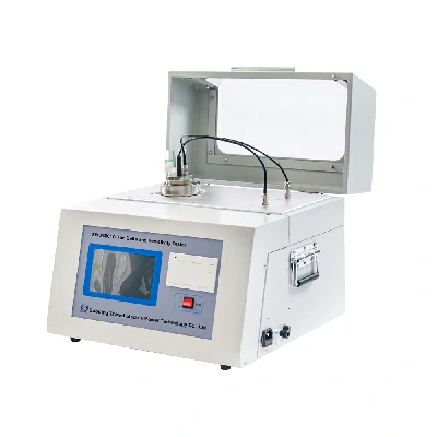
  1. Enclosed Test Chamber: Dielectric strength testing is typically conducted within a sealed or enclosed test chamber to contain any potential hazards associated with high voltage testing. This helps prevent accidental exposure to electrical arcs or sparks and minimizes the risk of injury to operators.
  2. Interlock Systems: Interlock systems are often implemented to ensure that the test chamber remains closed and secure during the dielectric strength test. These systems may include safety interlocks on doors, panels, or access points, which prevent the test from being initiated if the chamber is not properly sealed.
  3. Safety Shields and Barriers: Physical barriers or shields may be installed around the test chamber to provide additional protection against electrical hazards. These shields help contain any electrical discharges or arcing that may occur during the test, reducing the risk of injury to nearby personnel.
  4. Emergency Stop Mechanisms: Dielectric strength testing equipment is typically equipped with emergency stop buttons or switches that allow operators to quickly halt the test in the event of an emergency or safety concern. dielectric strength of oil These mechanisms provide a rapid means of shutting down the test and preventing further hazards.
  5. Grounding and Bonding: Proper grounding and bonding of the testing equipment and surrounding area are critical for minimizing the risk of electrical shocks and ensuring safe operation. Grounding electrodes or conductors are often used to dissipate electrical charges and provide a path for fault currents to safely discharge.
  6. Insulation and Isolation: Electrical components and conductors within the test chamber are insulated and isolated to prevent unintended contact with energized parts. Insulating materials and barriers help maintain electrical separation and reduce the risk of accidental contact.
  7. Safety Training and Procedures: Operators and personnel involved in dielectric strength testing should receive comprehensive safety training and follow established procedures for safe operation. This includes proper handling of high voltage equipment, adherence to safety protocols, and awareness of emergency response procedures.

By incorporating these safety features and practices, dielectric strength testing of oil can be conducted safely and effectively, minimizing the risk of electrical hazards and ensuring the protection of personnel and equipment involved in the testing process.

What are the software features of an flash point tester?

Flash point testers are devices used to determine the flash point of a liquid, which is the lowest temperature at which the vapor of a liquid ignites in the presence of an ignition source. While flash point testers primarily consist of hardware components for performing the test, some models may also include software features to enhance usability, data management, and reporting capabilities.

Here are some software features commonly associated with flash point testers:

  1. User Interface: Flash point testers may include a user-friendly graphical interface or software application that guides users through the testing process. The interface may provide intuitive controls, prompts, and instructions to help users set up the test, input parameters, and initiate measurements.
  2. Test Parameter Configuration: Software features allow users to configure test parameters such as test method, sample volume, heating rate, and test endpoint criteria. Users can select appropriate test methods (e.g., open cup, closed cup) and customize testing parameters based on the characteristics of the sample being tested.
  3. Data Logging and Storage: Flash point testers with software capabilities often include data logging and storage functionalities to record test parameters, measurement readings, and test results. Test data is typically stored in a digital format for easy retrieval, analysis, and reporting. Users can access historical test data, track trends, and generate reports for quality control and regulatory compliance purposes.
  4. Real-time Monitoring: Some flash point testers feature real-time monitoring capabilities that allow users to observe temperature changes, pressure variations, and other test parameters during the test process. Real-time data visualization helps users monitor test progress, identify anomalies, and make adjustments as needed to ensure accurate and reliable test results.
  5. Safety Features: Software features may include built-in safety protocols and alarm functions to ensure safe operation of the flash point tester. Users can set up safety thresholds, such as maximum temperature limits or pressure thresholds, and receive alerts or warnings if test conditions exceed predefined limits. Safety features help prevent equipment damage, sample spillage, and personnel injury during testing.
  6. Calibration and Maintenance: Flash point testers with software capabilities may include calibration and maintenance functions to ensure accurate and reliable test results over time. Users can schedule calibration checks, perform system diagnostics, and track instrument performance to maintain compliance with industry standards and regulatory requirements.
  7. Remote Control and Connectivity: Advanced flash point testers may offer remote control and connectivity features that allow users to operate the tester, monitor test progress, and access test data from remote locations. Connectivity options may include USB, Ethernet, Wi-Fi, or Bluetooth interfaces for seamless integration with laboratory information management systems (LIMS) or data acquisition systems.

Overall, software features enhance the functionality, usability, and efficiency of flash point testers by providing users with intuitive interfaces, data management tools, and safety mechanisms. These features help streamline the testing process, ensure data integrity, and facilitate compliance with industry standards and regulations.

How long does it take to perform a test using an ac hipot tester?


The time it takes to perform a test using an AC Hipot (high potential) tester can vary depending on several factors, including the specific test parameters, the complexity of the testing setup, and the characteristics of the equipment being tested.

Here are some factors that can influence the duration of a test using an AC Hipot tester:

  1. Test Voltage and Duration: The test voltage level and duration are significant factors in determining the overall test time. Higher test voltages or longer test durations typically require more time to complete. For example, testing at higher voltages may involve longer stabilization times and longer test durations to ensure accurate and reliable measurements.
  2. Test Setup and Configuration: The complexity of the test setup and configuration can affect the time required to perform a test. This includes factors such as the number of test points, the type and configuration of the test specimen or equipment, the connection method, and the setup of auxiliary equipment such as transformers, switches, or safety interlocks.
  3. Safety Procedures and Precautions: Safety procedures and precautions, such as equipment setup, safety checks, and verification of test connections, ac hipot tester can add to the overall test time. Ensuring proper safety measures are in place before initiating the test is essential for protecting personnel and equipment from potential hazards associated with high-voltage testing.
  4. Test Sequence and Procedures: The test sequence and procedures specified by the testing standards or protocols also influence the duration of the test. Sequential testing of multiple parameters, such as insulation resistance, dielectric strength, leakage current, and withstand voltage, may require additional time to complete each step in the testing sequence.
  5. Equipment Warm-up and Stabilization: Some AC Hipot testers may require a warm-up period or stabilization time before initiating the test to ensure optimal performance and accuracy. This warm-up period may vary depending on the specific tester model and manufacturer specifications.
  6. Data Collection and Analysis: After completing the test, additional time may be required for data collection, analysis, and interpretation of test results. This includes reviewing measurement readings, analyzing test data, and documenting test outcomes in compliance reports or test certificates.

Overall, the time it takes to perform a test using an AC Hipot tester can range from a few minutes to several hours, depending on the aforementioned factors. Proper planning, preparation, and adherence to established testing procedures are essential for efficient and accurate high-voltage testing while ensuring the safety of personnel and equipment involved in the testing process.

How does an contact resistance measurement handle oil samples with emulsions or mixtures?


Contact resistance measurements are typically performed on electrical contacts, connections, or conductors to assess their integrity and performance. While contact resistance measurements are not specifically designed to handle oil samples with emulsions or mixtures, the presence of such contaminants can affect the measurement process and results in several ways:

  1. Impact on Conductive Surfaces: Oil emulsions or mixtures containing contaminants can coat or contaminate the surfaces of electrical contacts, connectors, or conductors, leading to increased contact resistance. The presence of insulating or non-conductive substances in the oil can hinder electrical conductivity and affect the accuracy of contact resistance measurements.
  2. Surface Cleanliness: Contact resistance measurements require clean and dry contact surfaces to ensure reliable and accurate results. Oil emulsions or mixtures may leave residues or films on contact surfaces, interfering with electrical contact and leading to artificially high contact resistance readings. Proper cleaning and preparation of contact surfaces are essential to minimize the impact of oil contamination on measurement accuracy.
  3. Measurement Stability: Oil emulsions or mixtures can introduce variability or instability in contact resistance measurements due to changes in the composition, viscosity, or conductivity of the oil. Variations in oil properties may affect the electrical contact between measurement probes and test points, leading to inconsistent or fluctuating resistance readings.
  4. Interpretation of Results: When performing contact resistance measurements on oil-contaminated surfaces, it’s important to interpret the results cautiously and consider the potential influence of oil contamination on measurement accuracy. contact resistance measurement Anomalies or deviations in resistance readings may indicate the presence of oil-related contaminants or surface irregularities requiring further investigation or corrective action.

To address the challenges associated with contact resistance measurements on oil-contaminated surfaces, several strategies can be employed:

  • Surface Cleaning: Thoroughly clean and degrease contact surfaces to remove oil residues, contaminants, or films before performing contact resistance measurements. Use appropriate cleaning agents, solvents, or methods to ensure optimal surface cleanliness and electrical contact.
  • Surface Treatment: Apply surface treatments or coatings to protect contact surfaces from oil contamination and minimize the adhesion of contaminants. Anti-corrosion coatings, protective films, or barrier coatings can help maintain surface integrity and reduce the impact of oil-related contaminants on contact resistance measurements.
  • Measurement Techniques: Employ specialized measurement techniques or equipment designed to handle oil-contaminated surfaces and mitigate the effects of oil-related contaminants on measurement accuracy. Consider using techniques such as multiple-point probing, averaging measurements, or compensating for surface irregularities to improve measurement stability and reliability.

Overall, while contact resistance measurements may encounter challenges when performed on oil-contaminated surfaces, proper cleaning, surface treatment, and measurement techniques can help mitigate the impact of oil-related contaminants and ensure accurate and reliable assessment of contact integrity and performance.

How do super soft bedding sets contribute to a sense of luxury and indulgence in the bedroom?

Super soft bedding sets contribute to a sense of luxury and indulgence in the bedroom in several ways:

  1. Velvety Texture: Super soft bedding sets are often crafted from plush fabrics like microfiber, cotton sateen, or bamboo rayon, which have a velvety texture that feels incredibly smooth and luxurious against the skin. This softness enhances the overall comfort of the bedding, inviting users to sink into bed and relax.
  2. Elegant Appearance: Many super soft bedding sets feature a lustrous sheen or satin-like finish that adds an elegant touch to the bedroom decor. The smooth surface of the bedding sets creates a sleek and polished look, evoking a sense of sophistication and refinement.
  3. High-Quality Materials: Super soft bedding sets are typically made from high-quality materials that are carefully selected for their softness, durability, and breathability. These premium materials contribute to a luxurious feel and ensure long-lasting comfort and satisfaction.
  4. Attention to Detail: Luxury bedding sets often feature intricate details and thoughtful design elements that elevate the overall aesthetic of the bedroom. This may include embroidered accents, decorative stitching, or embellishments like piping or ruffles, adding visual interest and sophistication to the bedding.
  5. Tailored Fit: Super soft bedding sets are designed to provide a snug and tailored fit on the bed, creating a clean and polished appearance. super soft bedding set Fitted sheets feature deep pockets or elasticized edges to ensure a secure and wrinkle-free fit, while duvet covers and pillowcases are constructed with precision to maintain their shape and form.
  6. Temperature Regulation: Many super soft bedding sets are engineered to provide optimal temperature regulation, keeping users comfortably cool in warm weather and cozy and warm in cooler temperatures. This balance of warmth and breathability enhances the overall comfort of the bedding, contributing to a luxurious sleeping experience.
  7. Sensory Experience: The soft and luxurious feel of super soft bedding sets engages the senses and creates a sensory experience that promotes relaxation and indulgence. The tactile sensation of sinking into soft, velvety sheets and blankets can evoke feelings of comfort, tranquility, and well-being, enhancing the overall ambiance of the bedroom.

Overall, super soft bedding sets contribute to a sense of luxury and indulgence in the bedroom by providing unparalleled comfort, elegance, and sensory pleasure. The combination of high-quality materials, attention to detail, and thoughtful design elements creates an inviting and luxurious sleeping environment that promotes restful sleep and relaxation.

How does the surface finish of fire resistant paper affect its performance?

The surface finish of fire-resistant paper can have a significant impact on its performance in various applications.

Here’s how different surface finishes can affect the performance of fire-resistant paper:

  1. Smooth Surface: Fire-resistant paper with a smooth surface finish offers several advantages. It provides excellent contact with adjoining surfaces, ensuring a tight seal in gasketing applications. A smooth surface finish also facilitates the easy application of adhesives or coatings, enhancing bonding strength and durability. Additionally, smooth surfaces are less prone to collecting dust, dirt, or debris, making them easier to clean and maintain.
  2. Textured Surface: Fire-resistant paper with a textured surface finish may offer improved gripping properties and enhanced resistance to slippage in certain applications. The texture can help create a tighter seal in gasketing applications, especially in irregular or uneven surfaces. Additionally, textured surfaces may provide better traction for handling and installation, reducing the risk of accidental slips or mishaps.
  3. Matte Finish: A matte finish on fire-resistant paper can help reduce glare and reflection, making it suitable for applications where visual clarity is important. Matte surfaces are less likely to cause eye strain or discomfort, especially in environments with bright lighting conditions. Additionally, matte finishes can help minimize the appearance of fingerprints, smudges, or other surface imperfections, maintaining a clean and professional appearance.
  4. Glossy Finish: Fire-resistant paper with a glossy finish offers a smooth and shiny surface that enhances visual appeal and aesthetic appeal. Glossy surfaces may be preferred in applications where appearance is a primary consideration, fire resistant paper such as decorative or display purposes. However, glossy finishes may be more prone to showing fingerprints, smudges, or surface imperfections, requiring more frequent cleaning and maintenance to maintain their appearance.
  5. Embossed or Patterned Finish: Fire-resistant paper may feature embossed or patterned surface finishes for added visual interest or texture. Embossed patterns can create a decorative effect or enhance tactile properties, making the paper more visually appealing or easier to grip. However, embossed surfaces may also affect the paper’s ability to conform to irregular shapes or surfaces in certain applications.

Overall, the surface finish of fire-resistant paper plays a crucial role in determining its performance characteristics, including sealing properties, bonding strength, visual appearance, and ease of handling. The choice of surface finish should be carefully considered based on the specific requirements of the application to ensure optimal performance and durability.

What are the applications of malleable iron fittings dimensions in pneumatic systems?

Malleable iron fittings dimensions are commonly used in various applications within pneumatic systems due to their durability, strength, and versatility.

Some of the key applications of malleable iron fittings dimensions in pneumatic systems include:

  1. Piping Networks: Malleable iron fittings are widely used in the construction of piping networks within pneumatic systems. They facilitate the connection of pipes, tubing, hoses, and other components to create a network for conveying compressed air and other pneumatic fluids throughout the system.
  2. Distribution Manifolds: Malleable iron fittings are used to construct distribution manifolds or headers within pneumatic systems. These manifolds distribute compressed air from the main supply line to various branches or sections of the system, allowing for efficient routing and control of airflow.
  3. Valve Assemblies: Malleable iron fittings are employed in the assembly of pneumatic valve systems. They are used to connect valves, actuators, positioners, and other control devices to the piping network, enabling precise control over the flow, direction, and pressure of compressed air within the system.
  4. Pressure Regulation: Malleable iron fittings are utilized in the installation of pressure regulation devices such as pressure reducing valves, regulators, and relief valves within pneumatic systems. These fittings facilitate the connection of pressure control devices to the piping network, ensuring consistent and safe operation of the system.
  5. Air Treatment Components: Malleable iron fittings are employed in the installation of air treatment components such as filters, lubricators, and dryers within pneumatic systems. They allow for the integration of these components into the piping network, ensuring clean, dry, and lubricated compressed air for optimal performance of pneumatic equipment.
  6. Connection Points: Malleable iron fittings serve as connection points for various pneumatic components, including hoses, tubing, fittings, malleable iron fittings dimensions and adapters. They enable quick and secure connections between components, facilitating the assembly, maintenance, and repair of pneumatic systems.
  7. Instrumentation and Control: Malleable iron fittings are utilized in the installation of instrumentation and control devices within pneumatic systems, such as pressure gauges, flow meters, and control valves. They provide mounting points and connection interfaces for these devices, enabling monitoring and control of system parameters.
  8. Custom Fabrications: Malleable iron fittings can be used in custom fabrications and assemblies within pneumatic systems to meet specific application requirements. They can be welded, brazed, or threaded to create custom configurations, adapters, brackets, and supports as needed for unique pneumatic applications.

Overall, malleable iron fittings dimensions find widespread use in pneumatic systems across various industries, providing reliable and robust connections for the efficient conveyance, control, and distribution of compressed air and pneumatic fluids.

How are reslient seat gate valve tested and validated to ensure their compliance with industry standards and specifications?

Resilient seat gate valves undergo rigorous testing and validation processes to ensure their compliance with industry standards and specifications.

Here are the typical steps involved in testing and validating resilient seat gate valves:

  1. Material Testing: The materials used in the construction of resilient seat gate valves, including the valve body, gate, seat, stem, and seals, undergo material testing to verify compliance with relevant material standards. This involves testing for mechanical properties, chemical composition, corrosion resistance, and durability.
  2. Dimensional Inspection: Resilient seat gate valves are subjected to dimensional inspection to ensure that they meet the specified dimensions and tolerances outlined in industry standards and specifications. This includes verifying the dimensions of critical components such as the valve body, gate, seat, stem, and flanges.
  3. Pressure Testing: Resilient seat gate valves undergo pressure testing to assess their performance under various pressure conditions. This typically includes hydrostatic testing, where the valve is subjected to water or another suitable test fluid at a specified pressure to check for leaks, integrity, and pressure containment capabilities.
  4. Leakage Testing: Resilient seat gate valves are tested for leakage to ensure that they provide tight shut-off and prevent fluid loss when the valve is closed. Leakage testing involves applying pressure to the valve and monitoring for any signs of leakage past the sealing surfaces, including the gate-to-seat interface and the stem packing.
  5. Functional Testing: Functional testing is conducted to verify the operational performance of resilient seat gate valves under normal operating conditions. This includes testing the valve’s ability to open and close smoothly, operate at different flow rates, reslient seat gate valve and withstand cycling under varying pressures and temperatures.
  6. Endurance Testing: Resilient seat gate valves may undergo endurance testing to assess their long-term performance and durability. This involves subjecting the valve to repeated cycles of operation under simulated operating conditions to evaluate its resistance to wear, fatigue, and degradation over time.
  7. Temperature Testing: Resilient seat gate valves are tested to ensure their performance under different temperature conditions. This includes testing for temperature resistance, thermal expansion, and the ability to maintain sealing integrity at elevated or low temperatures.
  8. Material Compatibility Testing: Resilient seat gate valves are tested for compatibility with different types of fluids and operating environments to ensure that they can withstand exposure to various chemicals, solvents, and abrasive substances without degradation or failure.
  9. Corrosion Resistance Testing: Resilient seat gate valves are tested for corrosion resistance to assess their ability to withstand corrosion from exposure to corrosive media or environmental conditions. This involves subjecting the valve to accelerated corrosion tests or exposure to corrosive agents to evaluate its resistance to corrosion.
  10. Certification and Compliance: Once testing and validation are complete, resilient seat gate valves may undergo certification by third-party organizations or regulatory bodies to verify compliance with industry standards and specifications. This certification provides assurance to customers that the valves meet the required quality, performance, and safety standards.

By undergoing comprehensive testing and validation processes, resilient seat gate valves can ensure compliance with industry standards and specifications, as well as provide reliable and durable performance in various industrial applications.

What role does Mobile Grow Rack play in sustainable farming practices?


Mobile Grow Racks can play a significant role in sustainable farming practices by offering several advantages that contribute to resource efficiency, environmental conservation, and improved agricultural productivity.

Here are some ways in which Mobile Grow Racks can support sustainability:

  1. Space Optimization:
    • Mobile Grow Racks are designed to be movable, allowing for efficient space utilization. This mobility enables farmers to optimize the layout of their cultivation space, making the best use of available land and minimizing the environmental impact associated with large, fixed structures.
  2. Resource Efficiency:
    • By incorporating features like adjustable shelves and mobility, Mobile Grow Racks enable farmers to efficiently use resources such as water, light, and nutrients. These systems can be tailored to specific crop needs, preventing overuse of resources and minimizing waste.
  3. Energy Efficiency:
    • Some Mobile Grow Racks are designed to be integrated with energy-efficient technologies, such as LED lighting and climate control systems. This can result in lower energy consumption compared to traditional farming methods, contributing to sustainability and reduced carbon footprints.
  4. Crop Rotation and Seasonal Flexibility:
    • Mobile Grow Racks facilitate easy movement of crops, allowing for efficient crop rotation. Crop rotation helps maintain soil health, prevents disease buildup, and reduces the need for chemical inputs, promoting sustainable farming practices.
  5. Reduced Pesticide Use:
    • Controlled environments provided by Mobile Grow Racks can reduce the need for pesticides. By preventing exposure to external pests and diseases, China Mobile Grow Rack supplier these systems promote healthier crops, minimizing the reliance on chemical interventions.
  6. Year-Round Production:
    • Mobile Grow Racks, especially when used in conjunction with climate-controlled environments, enable year-round production. This continuous production can help meet demand consistently, reducing the pressure on seasonal farming and promoting a more stable and sustainable food supply.
  7. Water Conservation:
    • Precision irrigation systems integrated with Mobile Grow Racks allow for targeted and efficient water use. Water usage can be optimized based on crop requirements, reducing water wastage and contributing to sustainable water management practices.
  8. Adaptability to Urban Agriculture:
    • Mobile Grow Racks are well-suited for urban agriculture, where space is often limited. By utilizing vertical space and being easily movable, these systems enable farming in urban environments, reducing the need for transporting produce over long distances.
  9. Minimized Soil Erosion:
    • Mobile Grow Racks often operate in soil-less or container-based systems, minimizing soil erosion concerns. This contributes to the preservation of natural soils and prevents sediment runoff into water bodies.
  10. Reduced Land Footprint:
    • The mobility of these racks allows for concentrated and intensive cultivation in smaller spaces. This can reduce the overall land footprint required for agriculture, potentially preventing deforestation and preserving natural habitats.

While Mobile Grow Racks offer various benefits for sustainable farming, their effectiveness depends on factors such as the specific design, technology integration, and the management practices employed by farmers. It’s crucial to consider the specific features of the Mobile Grow Rack system being used and how they align with sustainable farming goals.

How does the size and scalability of Fix Grow Rack impact its usability?

The size and scalability of a growing system, such as a grow rack, can significantly impact its usability.

Here are some ways in which size and scalability considerations may influence the effectiveness of a growing system:

  1. Space Utilization:
    • A scalable design allows for flexibility in adapting to different space requirements. The ability to adjust the size of the system enables efficient use of available space, whether in a small indoor environment or a larger agricultural setting.
  2. Crop Capacity:
    • The size of the grow rack directly affects the number of plants it can accommodate. Scalability allows for the system to be expanded or contracted based on the desired crop capacity, making it adaptable to the specific needs of the user.
  3. Suitability for Various Crops:
    • Different crops have varying space requirements and growth characteristics. A scalable grow rack can be customized to accommodate the specific needs of different crops, promoting versatility and usability across a variety of plant types.
  4. Operational Efficiency:
    • The scalability of a system can impact operational efficiency. For example, in a commercial setting, the ability to scale up may increase overall production efficiency, while in a smaller setting, scalability allows for gradual expansion as needed.
  5. Resource Efficiency:
    • A well-designed, scalable grow rack can contribute to resource efficiency by allowing users to optimize the use of space, water, and nutrients based on the scale of cultivation. This is particularly important for sustainable and resource-conscious farming practices.
  6. Adaptability to Growth Stages:
    • The ability to adjust the size of the grow rack is beneficial for accommodating different growth stages of plants. For instance, the system can be expanded as plants mature, providing adequate space for their development.
  7. Technology Integration:
    • Scalable systems may integrate advanced technologies more seamlessly. This can include automation, monitoring systems, China Fix Grow Rack supplier and data collection tools that enhance the overall usability and efficiency of the growing process.
  8. Cost Considerations:
    • Scalability can impact the initial cost and ongoing operational expenses. Users can start with a smaller system and expand as needed, potentially reducing upfront costs and allowing for a more phased approach to investment.

It’s important to note that the specific impact of size and scalability on usability can vary depending on the design and intended use of the particular growing system, in this case, the “Fix Grow Rack.” For accurate and detailed information, it’s recommended to refer to the product documentation or contact the manufacturer directly.